SHOALOS BUNDLE
Four SDKs around the payload.
Software layer connects payload setup, perception, swarm state, and mission control — from onboard sensor drivers to the partner SDKs, across eight layers.
Explore the architecture ↓
Select a component or software layer to explore its responsibilities.
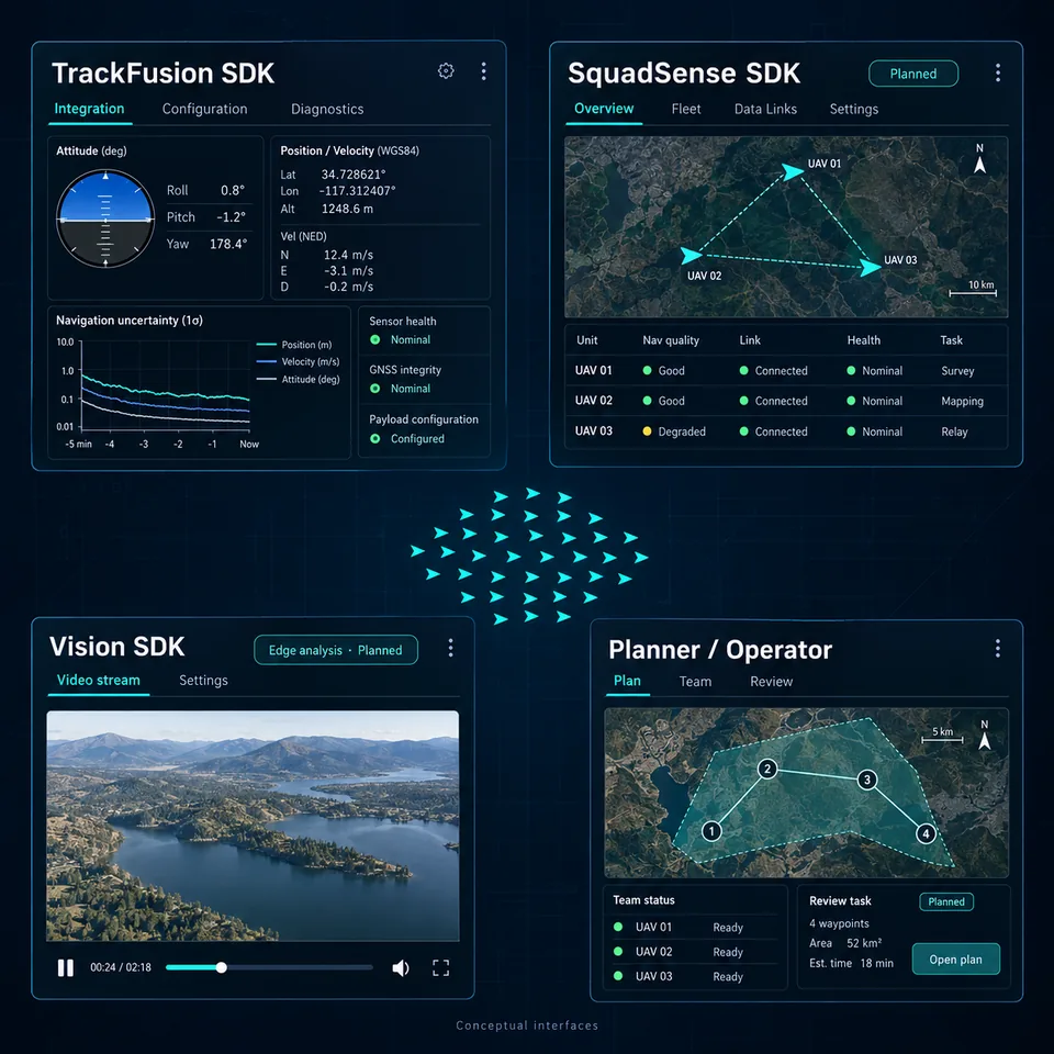
The ShoalOS Core Platform SDKs. The TrackFusion SDK configures the payload and exposes navigation data to the host aircraft. The SquadSense SDK shares position quality, link status and system health across the team. The Vision SDK streams video and enables planned edge ATD/ATR workflows.
Together with L0, the SDKs define the integration work required for each partner.
Fleet registry, health and telemetry, firmware updates, key management, audit and the operator UI. Planned mission deployment transfers the flight plan and payload reference data to their respective destinations, then records the loaded versions.
Nav Planner authors and reviews the flight plan before flight. The planner / operator view prepares routes, monitors team state, reviews outcomes and reassigns tasks. OspreyVMS handles video viewing, recording and evidence; the proposed integration brings thermal video and object tracks back to operator workflows.
View Nav Planner →Reference retrieval, image conversion, tiling and the mission data store. The proposed mission package associates the reviewed route with terrain references, thermal reference imagery and payload configuration for onboard use.
View RECONN.EARTH →The payload can sense the nearby squad and share navigation confidence and payload health over the secured data link. Systems can retask available resources in response to a failed sensor, drone or mission objective.
Next development stage: implement and integrate SquadSense.
View SquadSense →Onboard reference cache, waypoint context, drift monitoring and fallback policy. Navigation runs continuously; reference matches correct and cross-check the estimate. The host autopilot executes the flight plan and retains flight control.
Dynamic rerouting is a planned integration for mission-time route updates. It belongs in navigation services, with the host retaining flight-control authority.
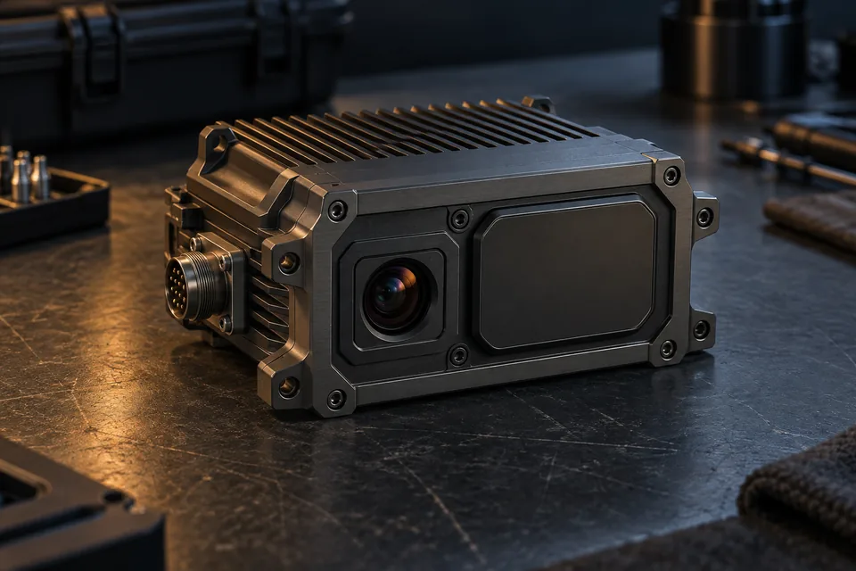
Proposed hardware view →IMU motion prediction, the radar altimeter ground profile, radar map matching for drift correction and a thermal scene check against the reference scene. A position fix is accepted when radar and thermal agree; GNSS is a check only, never used to navigate.
An FPGA system-on-chip — fixed-timing logic and ARM cores — is the intended implementation. Integrated timing and the operating envelope require validation.
View TrackFusion →Drivers and interfaces for IMU, barometer, airspeed, radar altimeter, imaging radar and thermal camera, with GNSS as a check input. Autopilot interfaces cover PX4, ArduPilot and MAVLink, alongside gimbals and radio links.
OEM integration at this layer connects each vehicle’s sensors, actuators and communications hardware.
Nav Planner exports the route. Reference packaging and verified loading into the vehicle are planned integration steps.
The IMU predicts motion. Radar map matching corrects drift, the thermal scene check confirms the fix and GNSS is a check only.
Mission data feeds the applications; health, telemetry and audit records feed the control plane.
Watch the flight simulation and follow a mission through a GNSS outage.